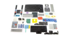
What is a Membrane Switch?
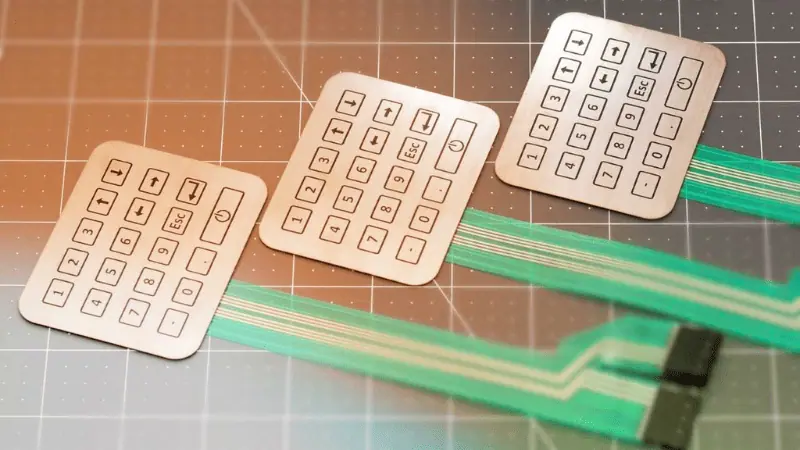
A membrane switch is an on/off switch printed on a flexible sheet (membrane) using conductive inks. The circuitry is printed in a special interdigitated pattern that results in open circuits. The keypad layer on top houses conductive pills that close these circuits upon key presses. It is most commonly used in the manufacturing of silicone rubber keypads.
A typical membrane switch consists of multiple adhesive, plastic, and silicone layers. The top layer of any membrane switch is a graphical overlay. At the same time, the bottom layer is almost always some form of sealant or adhesive.
Aside from flexible bases, membrane switches can also be printed on PCBs (Printed Circuit Boards). The PCB backing gives rigidity and durability to the membrane switch. The circuit board is not flexible, but undeniably a member of the membrane switch family since it works on the same basic principle.
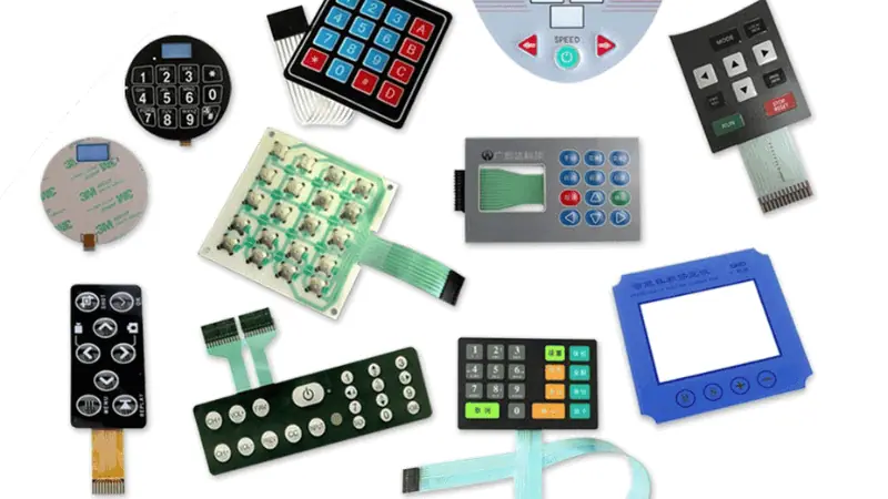
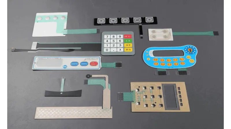
Examples

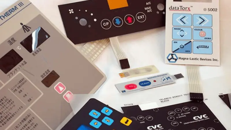
A membrane switch can be used in any application that requires a thin profile keypad. The most common examples of membrane switches are as follows.
- TV Remotes
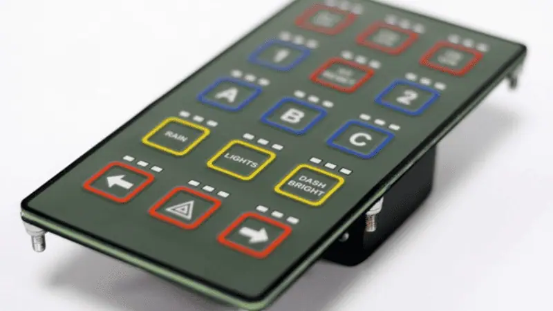
- Car Dashboard Buttons
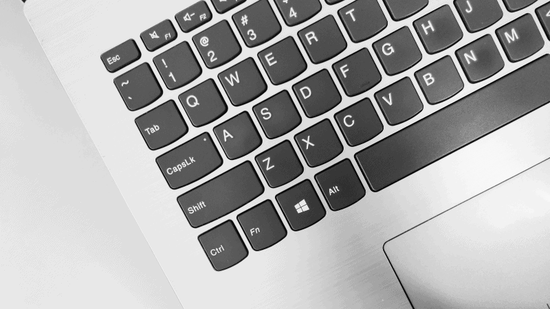
- Membrane Keyboards
- Silicone Rubber Keypads for Calculator
Types of Membrane Switches
Membrane switches can come in different shapes and forms. Most changes come in the form of design considerations. Following are the basic types of membrane switches.
1. Non-Tactile Switch
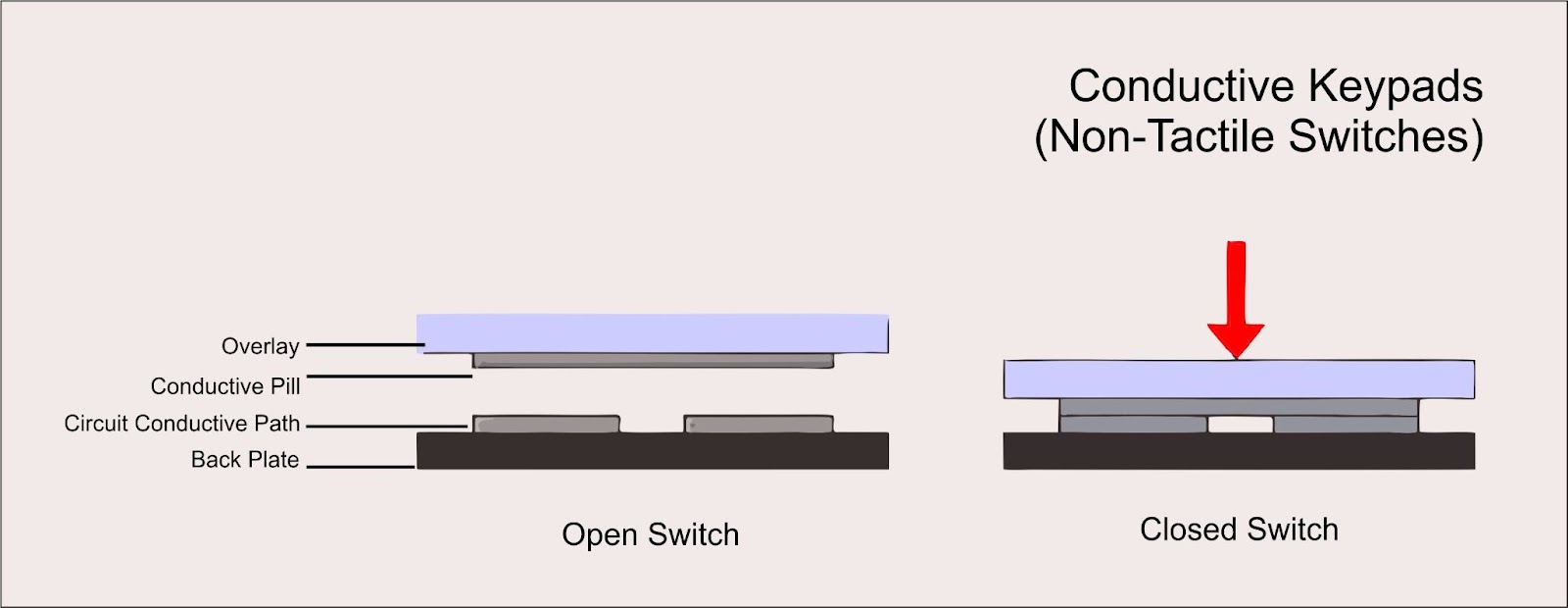
Non-tactile membrane switches have a conductive pill on the bottom of the keypad layer. These pills combine tiny conductive particles into a non-conductive rubber base.
Each key has a conductive pill under it, and pressing the key results in the pill contacting the circuit. Once the pill comes in contact with the circuit, it immediately closes the open circuit, resulting in on/off functionality.
The most common housing for the conductive pills is a thin, flexible keypad layer of silicone. This thinner silicone does not have good tactile feedback. Hence the non-tactile naming scheme.
Tactile feedback is the physical response from the keypad upon button press. You can think of tactile feedback as a small bump you feel when pressing a button.
Conductive Rubber Keypads

Non-tactile switches use a conductive pill to trigger the circuit “On” or “Off.” When this switch type is assembled into a keypad, it becomes a non-tactile membrane keypad. You will often see a non-tactile membrane keypad called a conductive rubber keypad.
Keypad construction for a non-tactile switch is much easier and cheaper. Making them very popular among keypad designers.
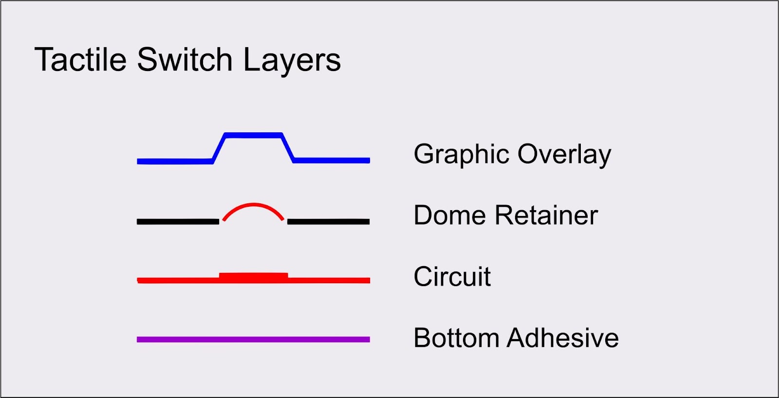
2. Tactile Switch
Tactile switches use conductive metal domes to trigger the circuit On/Off. These metal domes have a higher deformation resistance, resulting in a sharp snap upon key press.
The metal domes are more resilient than conducive pills. Making them particularly useful for applications in harsh environments. The dome sizes range from 4mm to 25mm and come in various thicknesses and actuation forces.
A cheaper alternative to metal domes is polyester domes. They provide tactile feedback on par with stainless steel domes but have poor thermal resistance.

Non-Conductive Rubber Keypads
Non-conductive rubber keypads act as mechanical actuators pushing against the metal dome. The base design of these keypads is very similar to conductive keypads. The only two differences lie in silicone thickness and conductive pills.
Non-conductive keypads don’t need housing pills and use thicker silicone for construction. These keypads are preferred for their superior tactile response and longevity.
PCB Backed Switch
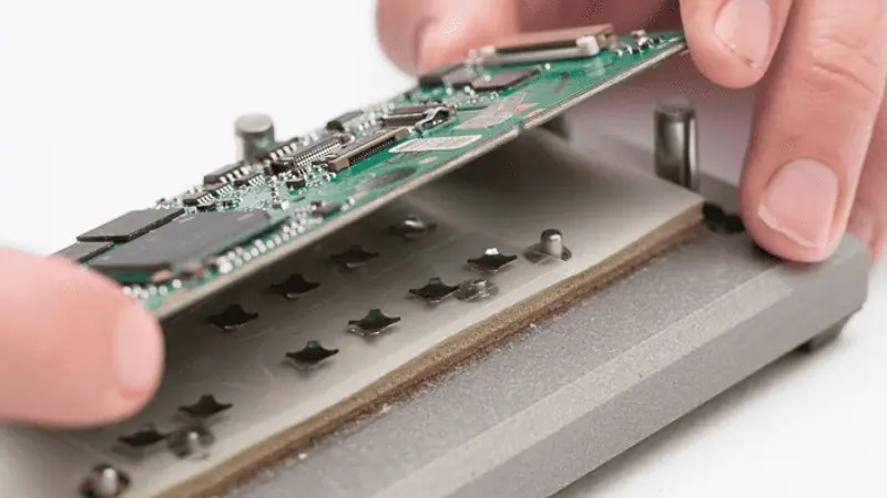
Some membrane switches use a rigid substrate as a base for the circuit. Instead of printing the circuit on a flexible Polyethylene terephthalate (PET) sheet, you use a stiff composite board. The board provides structural strength to the keypad.
The PCB also acts as a mounting surface for additional electrical components. PCB-backed switches make the job of electronics design engineers easier. A PCB is compatible with both tactile and non-tactile switches.
PCB is not a type of membrane switch. Instead, it is a material choice. This membrane switch design guide will only consider PCBs as an addition to tactile and non-tactile switches.
How to Design Membrane Switches
Designing your own membrane switch requires careful consideration, including considerations such as cost analysis, material selection, and surface finish. These are among the most important factors to consider when creating a switch design.
Switch Type
As discussed previously, a membrane switch has two main types. Select the switch type that is best suited to your application.
Here is a simple table summarizing the difference between the two switch types.
| Features | Tactile Switches | Non-Tactile Switches |
|---|---|---|
| Cost | Higher | Lower |
| Keypad Thickness | Thicker | Thinner |
| Tactile Feedback | Excellent | Poor |
| Durability | Higher | Lower |
| Conductivity | Non-Conductive | Conductive |
Additional switch design choices include PCB or PET circuit bases. PCB-backed switches are your only option if your application requires a sturdy keypad design.
Material Selection
Different parts of a membrane switch can be constructed using different materials. The following are some basic material choices for switch design.
Overlay Materials
The overlay is a thin layer of material that sits atop the membrane switch. It acts as an interface for the switch and as a visual and graphic design canvas. The overlay layers can be composed of various materials.
- Polycarbonate (PC) is a popular material choice for overlay designs. You can easily die-cut a PC. It is also suitable for printing and embossing. Polycarbonate is a cost-efficient material suitable for almost any application.
- Polyester is a good alternative for overlay designs. It has decent chemical resistance properties aside from its flexibility and long lifespan.
- Silicone keypads are a good alternative to plastic overlays. It has a soft touch feel and distinct individual keys.
Coating
Overlay materials are fairly strong in most situations but they will wear out over time. Coating the overlay in harder material is a simple way to increase durability. There are three common types of hard coatings.
- Textured: Useful for hiding fingerprint marks.
- Glossy: Excellent scratch resistance and useful for glare minimization.
- UV Protection: Protects the overlay from fading or discoloring under sunlight.
Ink Materials
Conductive Ink is a mixture of a liquid base and tiny conductive particles. The particles are evenly distributed across the ink, making the ink electrically conductive. Circuit paths printed using conductive ink act are essentially thin wires.
The following conductive materials are commonly found in circuit printing ink.
- Copper
- Silver
- Graphite (Carbon)
Copper has a higher electrical conductivity but is also considerably expensive. Thus, copper is often restricted to special applications where electrical performance is a key factor.
Circuit Layer Materials
The circuitry layer is the base on which circuit diagrams are printed, using conductive inks. These layers can be made using almost any material as long as the printed circuits are consistent.
- Polyethylene Terephthalate (PET)
- Indium Tin Oxide (ITO)
- Composite Boards (PCB)
PET and ITO are flexible plastics. They are very common in membrane switch designs. The typical thickness for the circuit layers is between 0.003 – 0.010 inches (0.076 – 0.254 mm). These materials have higher durability and flexibility, making them excellent choices for outdoor applications.
PCB-based switches are preferred for their increased rigidity. They are ideal for high-performance applications where the keypad is non-stationary, such as a wireless remote.
Graphic Overlay Designs

Graphic overlays can be customized in a few ways. We previously discussed material choices for said overlays. But now, let’s focus on design elements printed on the polycarbonate overlays. Your choice of overlay design will affect switch costs.
The following are the most common techniques for printing graphic overlays.
Silk Screening
Silk-screen printing is the process of using a fine stencil mesh to impart paint onto a surface. Silkscreens are widely used in the switch industry, particularly in legend printing on graphic overlays.
Silk-screen printed legends are resilient and can last for decades without fading or wearing. Silk screening can also help add color to your graphic overlays. Since silk screening is a method of imparting paint to a surface, it is compatible with both PET and Silicone graphic overlays.
Embossing
Embossing is the process of creating raised surface patterns. Embossing results in a textured finish to the graphic overlays.
Embossing is generally more expensive than silk-screen printed designs. And offers very little advantage over silk screening or digital printing.
Embossing is reserved for special applications, such as adding braille textures for better accessibility. Almost every membrane switch in the market has small embossed areas around keys. Additionally, you can use embossing to add a premium feel to your graphic overlay.
Laser Etching

As the name suggests, laser etching uses a high-powered laser to burn a pattern or design into the graphic overlay. Laser etching is the opposite of embossing, resulting in engraved legends instead of raised ones.
Laser etching or laser engraving is a popular method of imparting permanent designs into the graphic overlay. They will never naturally fade, but they can get scratched off. Laser-etched designs are engraved into the material, and removing the lettering requires destroying the graphic layer.
Types of Tolerances
Tolerances are guidelines for the maximum allowable charge to a given property. Dimensional tolerances are defined as the percentage of the total length.
A tolerance of “+/- 0.01mm” for a 10mm long membrane switch means the total length of the membrane switch will be between 9.99 and 10.01 mm.
Mechanical Tolerances
Most membrane switches are cut using steel rule dies. The dies have an internal tolerance of 0.005″. These tolerances are subject to change depending on certain dimensions. The following are standard tolerances for the membrane switch manufacturing process.
- Standard +/- 0.015″
- Critical Dimensions +/-0.010″ (Perimeters and Cutouts)
- Hole Cut Tolerances +/-0.005″ (Hole center to hole edge)
Switch layers are typically smaller than the overlay. All layers underneath the overlay will be 0.015″ inset, from all edges and cutouts.
Laser Cutting Tolerances

The standard tolerance for laser cutting is +/-0.002″. Laser cutting is recommended for low-volume productions since it bypasses the tooling cost.
Actuation Tolerances
The typical actuation forces required for membrane switches are 170 to 680 grams. The two dome technologies will have higher basic performance specifications.
- Polyester Domes: 400-680 gm
- Stainless Steel Domes: 340-510 gm
Standard Actuation Tolerances is +/- 85 gm
Circuit Design

Proper circuit design will result in a more efficient layout of keys and liquid crystal displays (LCDs). Circuits need to be designed to maximize the space efficiency of a switch.
Circuit Layout
Your circuit should be designed so that each key is at least 1mm away from the other. Proper distance will result in proper action force for each switch. This will also prevent any unnecessary key presses.
A matrix configuration is generally the preferred layout for any membrane switch design guide. Part of the reason is to allow locating holes to be placed in the keys at the matrix nodes. Matrix layouts are some of the simpler circuit layout designs, as all the keys are arranged adjacent.
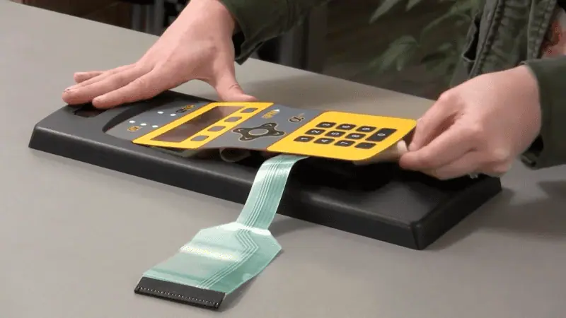
Tail Connectors
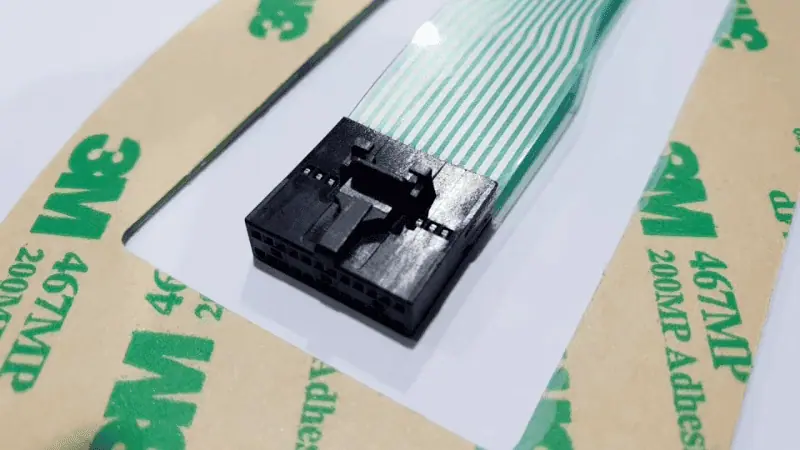
A tail connector is the most important part of any membrane switch design guide. The tail carries the switch on/off information from the circuit to the device.
The tail connectors must not be designed to crease or fold upon installation. A damaged tail connector will result in a defective switch.
The following are common tail connectors used in membrane switch designs.
- Berg/FCI Connector
- Molex Connector
- CrimpFlex Connector
- Solder Tabs
- Amp Connector
- ZIF Connector
- Male/Female Connectors

Display Cutouts
Display cutouts or windows are unnecessary for a membrane switch design since they are often optional design choices. Most devices use a separate display panel and a separate switch panel.
But if your application requires an LCD/LED display to be incorporated into a membrane switch, you need display cutouts.
The display window is the transparent window built into a switch to allow the LCD to shine through. Everything under the display windows must have the LCD shape cut out.
Display windows can have an antiglare characteristic to improve visual clarity and inhibit fingerprint marks. Your LCD needs to be as close to the window as possible. The further away your LCD is from the window, the more visual distortion will occur.
The visuals will be eligible if your LCD is 1.5mm away from the display window. But for any distance greater than 1.5mm, you will need anti-glare or glossy coating windows to compensate for the visual distortion.
Backlight
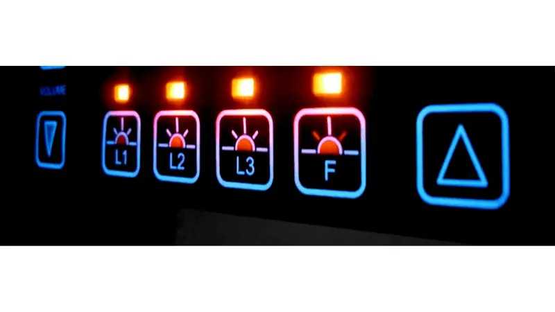
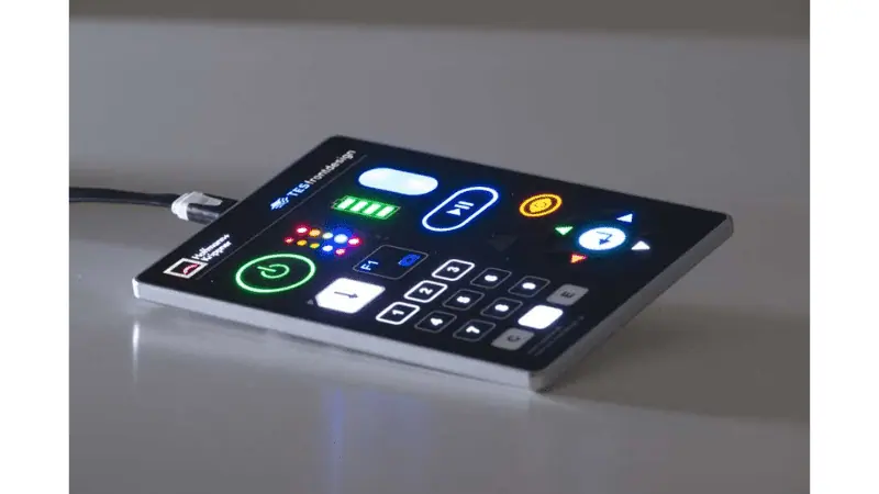
Backlight is an important feature that improves the overall effectiveness of a membrane switch. Backlighting provides soft illumination to the membrane switches, exponentially increasing nighttime visibility.
To properly backlight a membrane switch, a transparent overlay is necessary, and after silk screening, any non-printed area left will act as a light pass-through.
The actual source of the backlight can be customized according to user preference. The following are some common backlighting options for a membrane switch.
Optical Fibers
Optical fibers offer many advantages for backlighting a membrane switch.
- Low Profile
- Low Power Consumption
- Uniform Lighting
- EMI & RFI Resistance
- Long Lifespan (up to 100,000 hours)

Additionally, optical fibers are excellent for deployment in harsh environments. They have a wide operating temperature range and are well suited for high moisture and humidity environments.
Electroluminescent (EL) Lamps
Electroluminescent Lamps are materials that emit light when exposed to a strong electric field. Unlike most light fixtures, EL lamps don’t operate on thermal energy-to-light conversion.
- Compact Design
- Lower Cost
- Half-Life (3,000 – 8,000 hours)
EL lamps slowly degrade over time. As the material reaches its half-life, the brightness starts to fade.
Light Emitting Diodes (LEDs)
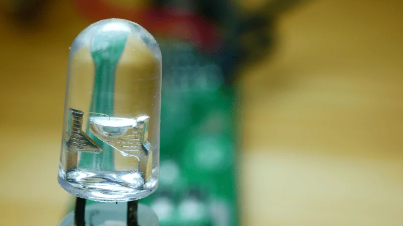
LEDs are the standard option for most low-profile applications. They can be installed in almost any application, but some will benefit more from their use.
- Robust
- Bright
- Low Power Consumption
- Long Lifespan
LEDs do not come with a built-in diffuser, often resulting in bright spots.
Electrical Specifications
A membrane switch can have any number of variations and customizations to suit different applications. But some general specifications remain the same.
| Properties | Specification |
|---|---|
| Switch Contact Voltage & Current | 28v DC & 30mA |
| Maximum Loop Resistance | 100 Ω |
| Switch Configuration | Single Pole Single Throw (SPST) |
| Contact Bounce | <200 ms |
| Display (LED/LCD) | Unit-specific values. |
| Non-Tactile Switch (Circuit) Thickness | ~0.75mm |
| Tactile Switch (Circuit) Thickness | >0.75mm |
Actuation Force
A membrane switch’s standard actuation force (170-680 gms) is adequate for most applications. However, specific applications may require a higher or lower actuation force. Luckily, most membrane switches can be easily configured for different actuation forces.
Here is a simple guide to an actuation force.
| Actuation Force | Grams of Force | Description | Example |
|---|---|---|---|
| Light Actuation Force | 85-170g | Suited to high-speed data entry. | Security Systems |
| Medium Actuation Force | 280-400g | Standard operating force for most applications. | Medical Device Testing Equipment |
| Heavy Actuation Force | 450-550g | Dissuade accidental key presses. Suited for users wearing protective equipment, such as thick gloves. | Industrial Applications |
Shielding
Shielding protects a membrane switch from unnecessary electrical interference, like ESD (Electrostatic Discharge) & EMI (Electromagnetic Interference). A typical membrane switch will work perfectly fine without shielding. However, for most high-performance applications, there is a significant difference in membrane switch lifespan.
Types of Shielding
The three most common types of membrane switch shieldings are as follows.
- Foil Shielding. Polyester or aluminum foil laminated with a non-conductive material.
- Transparent Film Shielding. See-through shielding is useful for window protection. This type of shielding is typically more expensive as well.
- Screen Printed Shielding. Silver or carbon conductive ink is printed in a unique pattern on a membrane switch to reduce electrical interference. A grid pattern is commonly used for decent coverage while using the minimum amount of conductive ink.
Shield Grounding
Shielding needs to be grounded so it can discharge any accumulated static charges. There are several ways to terminate/ground the shielding on a membrane switch.
- Tab Grounding. The shielding is connected to a small tab or stud attached to the backplate or metal enclosure. This is an easy and reliable method of terminating your shielding.
- Connector Grounding. The shielding is terminated at the tail exit point of a membrane switch.
- Full Enclosure Grounding. A membrane switch is covered in shielding material on all sides. This wrap-around method is the most reliable form of shielding termination, but it is very costly due to the added material and labor costs.
Your membrane switch applications determine your choice of shielding and termination.
Sealing
Switch sealing is a common step in the membrane switch design and construction phase. As the name suggests, a membrane switch is coated in water-tight, non-conductive materials and sealed shut. Sealing improves the longevity of a membrane switch exponentially.
Gasketing
Adding gaskets is another type of sealing technique for membrane switches. Instead of sealing the entire switch, you add a gasket along the perimeter of the enclosure.
Chemical Resistance Properties
Membrane switches are generally very resilient to environmental concerns. But chemical damage can occur and destroy the switch from the inside out. Sealing is an excellent method of increasing the corrosion resistance of a switch.
Adhesive Layers
Adhesives are often the most expensive material in any membrane switch by volume. Due to the low-profile nature of membrane switches, screws and clips are unusable. Each membrane switch layer must adhere to the other using a strong adhesive.
The industry standard for adhesives comes from the 3M Company. 3M’s excellent 467MP adhesive is the apparent choice for smooth surfaces. While rougher surfaces will benefit from 3M’s 468MP adhesive.
Be mindful of the fact that these are just standard adhesive choices. Your membrane switch design may benefit more from a different type of adhesive altogether.
Durability
A membrane switch’s durability is measured in cycles. Each cycle corresponds to one complete key press. The overall life cycle of a membrane switch must be around 1,000,000 cycles.
Life Cycle Testing
Life cycle testing is a simple way of determining the switch’s durability. If you use polycarbonate for your membrane, test its life cycle before finalizing any specifications. If the Life cycle data shows failure before the 1,000,000th cycle, then PC is not a suitable material for your particular membrane switch design.
You can also use the life cycle testing for material coating and adhesive choices. Some materials will result in a superior life cycle for certain applications. While those same materials will result in a poorer life cycle for a different application.
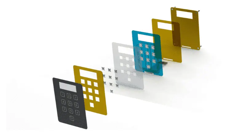
Membrane Switch Construction
Membrane switches are a collection of layers adhered together to form a single human-machine interface. The actual switch is just the printed circuit. However, without any of the additional layers, the printed circuit cannot function.
Following are the basic layers involved in the membrane switch design.
Layer 1: Graphic Overlay
The graphic overlay sits on the top of any given membrane switch. The graphic layer labels all the individual keys and additional instructions for device operation. Screen and digital printing are both viable options for graphic overlays.
Layer 2: Graphic Overlay Adhesive
This adhesive layer keeps the graphic overlay firmly attached to the membrane switch. This layer houses venting holes for dome switches, allowing proper airflow after each keypress.
Layer 3: Printed Top Circuit
The circuit is printed on this layer using conductive inks. This layer can be made from flexible PET or the right PCB. It is important to align this and the graphic layer as closely as possible. Mismatched layers will result in misclicks.
Layer 4: Separator Layer
The separator layer is an optional addition to any membrane switch design. But for most users, it is best not to skip this step. Separator layers ensure the printed circuit doesn’t contact any additional electronics in a membrane switch.

Layer 5: Printed Bottom Circuit (Optional)
Some complex switches require multiple circuit layers to fit the maximum number of keys in a smaller package. A non-conductive layer separates the two circuit layers.
Layer 6: Adhesive Layer
An adhesive layer is used for attaching the membrane switch to a backplate or mounting bracket.
Layer 7: Backplate
A rigid plate attaches to the base of a switch to increase structural integrity. Backplates are optional since most membrane switches are attached directly to the host machine. Wall-mounted switches use a separate mounting bracket instead of a backplate.
Layer 8: Shielding (Optional)
Shielding is often combined with the backplate to provide EMI and ESD protection.

Conclusion
Membrane switch designs are the critical interface where innovation meets reliability. By blending material expertise, precision engineering, and user-centric design, these components ensure seamless operation in industries from medical devices to industrial controls.
Staying ahead of trends and standards isn’t just optional. It’s what allows us to deliver durable, cost-effective, and future-ready solutions that keep your products competitive and trusted. Excellence in membrane design isn’t a detail; it’s a strategic advantage.
Design High-Performance Membrane Switches: Perfect Fit for Your Product!
At Hongju Silicone, we simplify your membrane switch design process with expert guidance. Our solutions ensure precise tactile response, durable construction, and customized aesthetics tailored to your needs. With rigorous testing and compliance certification, we deliver reliability that enhances user experience and extends product life.
Request a free design consultation and prototype quote today! Let’s create switches that elevate your product!